Category Archives: Modifications

Commodore Mouse Converted into Stealthy Wireless Mouse

This entry was posted in Build, Modifications on .
IMG_2624

IMG_2621

This commodore mouse was given to us by awesome Pat Dowd of Wavy TV, Thanks Pat!  This mouse was begging for attention from the day Pat donated it and many other vintage electronics.  A year later I broke the scroll wheel ]button on my mouse, it was a very nice mouse with over 30 feet in range. I decided the rest of it could be used in the commodore mouse.  I wanted to make this mouse a gimmick for messing with people, particularly my peers and geek friends.  Below shows the guts of the two mice:

IMG_2546 IMG_2548 IMG_2565

The idea I came up with was to retain the original cord and “look” of the mouse, but to also retrofit the plug to fit the mini USB bluetooth dongle within it, as well as make it cordless when I wanted.  So first and foremost I wanted stock look AND sound.  This meant I needed to keep the original hardware behind the buttons of the commodore mouse.  I decided after careful inspection that simply cutting the buttons off of the stock PCB was the easiest way to retain the sound and feel of this ancient technology.  To tie the old in with the new I simply Googled the switch data sheet from the new mouse and then made appropriate bridges from the Commodore buttons.  After gutting the other mouse and measuring it up against the Commodore mouse, I decided where to place things and located them carefully while hot glue was used to hold things together.

IMG_2550 IMG_2557 IMG_2560 IMG_2561 IMG_2570 IMG_2572 IMG_2574 IMG_2575 IMG_2576 IMG_2577 IMG_2578 IMG_2582 IMG_2585

Emptying the original DB9 port was a simple matter is this thing was designed to come apart with a couple sharp tools.  Then some Dremel work finished off the job.  Hot glue once again is used to hold the usb dongle in place.

IMG_2616IMG_2609IMG_2601 IMG_2600IMG_2602IMG_2603 IMG_2604IMG_2607IMG_2608

Finally, to maintain the look of a wired mouse I decided to shove a couple of Bucky Ball magnets into the original wire.  One ball resides at the mouse and the other is on the cord.  Because this mouse is actually wireless, I kept the cord very short.  Keeping the cord short also confuses people who are used to desktop length corded mice.


IMG_2586IMG_2597IMG_2598IMG_2610IMG_2611IMG_2613IMG_2615IMG_2614IMG_2625

Finally I have a completed fake wired, wireless mouse hidden within this ancient Commodore mouse!  Now I simply need the opportunity to confound someone.  Thanks for watching another quality build brought to you by Hot Glue.

IMG_2623 IMG_2622 IMG_2624 IMG_2626


Carnival Sign Mod

This entry was posted in Modifications on .

The organizers of Red Bull Creation made a wonderful sign for each of the teams represented at NYC Maker Faire 2012. Once we arrived home we lamented about the fact our new found sign would cost 350 watts to run. After some thinking, we decided to upgrade the sign to use less power and looks 10 Internets better!

How we did it:

We started with a simple plug in sign with all lights on. It was cool, but a little boring. We got back from Maker Faire, and we got to work on fixing that.

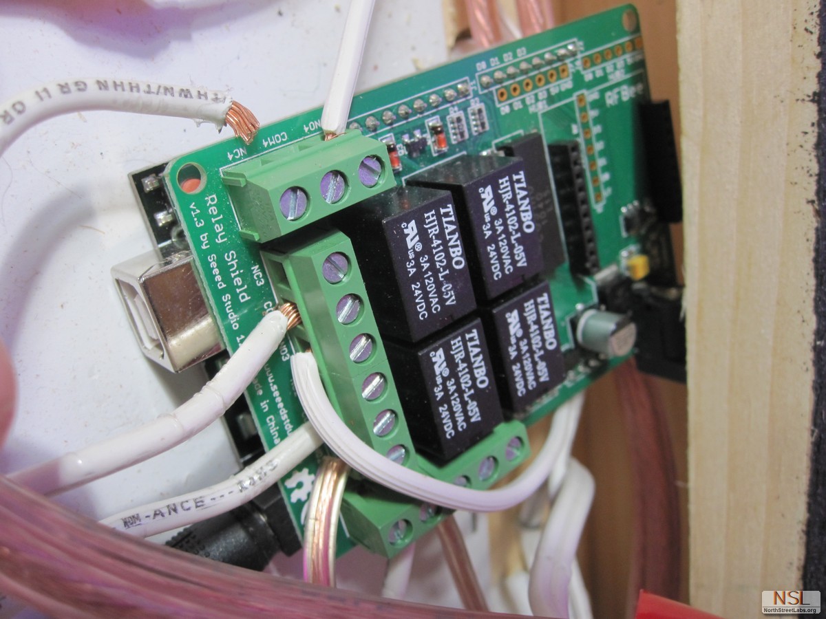
We quickly realized we had most of the supplies at our place already: An Arduino UNO and a Relay shield. We had been using the same relay shield to activate 12v winner lights on our spinning Centrifury game. We started by checking out the specs on the individual relays to see if they could take the load of the old fashioned bulbs. The 4 relays on the shield could handle 120v & 3A and could turn on the whole array when combined.

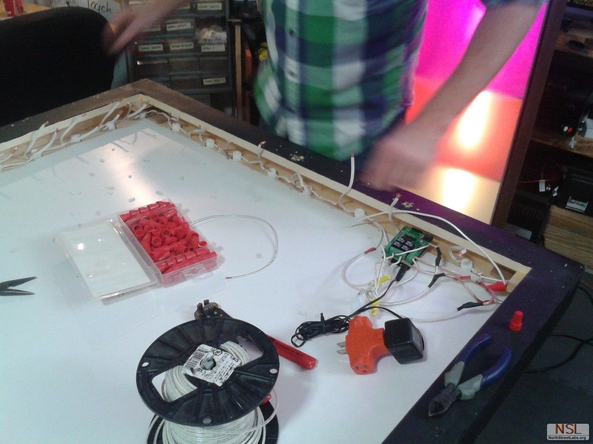
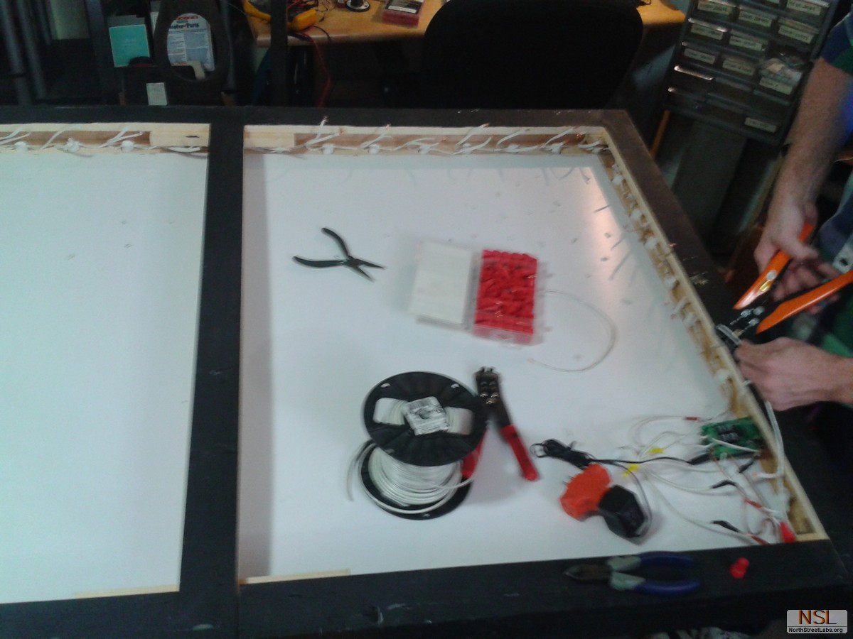
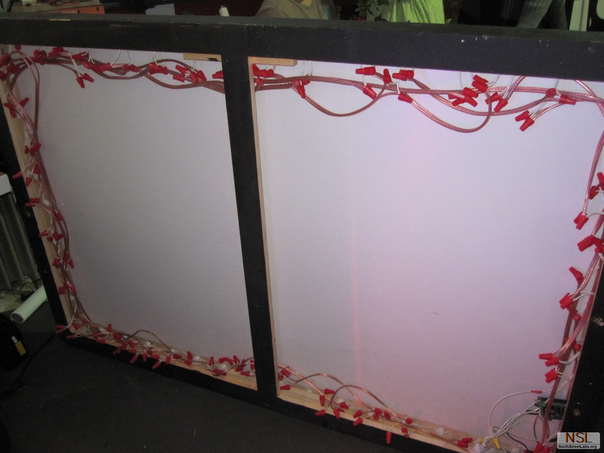
We had the idea of using simple persistence of vision. Wire every 4th bulb in a sequenced chain around the sign. To clarify, the actual wiring is done in parallel. This was the tedious part: lots of wire extensions, cutting, and combining. Our test program simply turned on one light at a time in sequence, leaving the other 3 off. When a sequence is completed, it gives the illusion of continuing down the chain as the loop starts over. Once we got that working, we switched directions for another effect. Then we added increasing/decreasing amounts of lit bulbs. For a final effect, we flashed all on/off in a slow strobe. Final connection of relays being done:

The relays should reliably handle 100,000 cycles. At the programmed rate, they will last for at least 48 hours! It’s great for short events, and relay boards aren’t that expensive.

We used the lazy man way of connecting due to time constraints. We still had blisters by the end from adding all of the extensions.

Here is the code for someone who wants to make something similar: RELAYtest

Thanks for reading!