Today we have launched our first Kickstarter, the Light of Legends! This epic lamp is an ambient mood lighting experience with 16 selectable colors of the rainbow and 4 different fade and flash modes! For sustainability we have combined energy efficiency LEDs with natural bamboo through sleek design. Click Here to learn more about the Light of Legends – lighting of the future!
Backstory: Red Bull recently sent us a fancy shield for an Arduino, dubbed the “Turbull Encabulator”. This is a play on a joke engineering video that used a bunch of technical jargon that made no sense whatsoever. Nevertheless, this board was packing a ton of potential, (which others have covered in detail elsewhere).
Basically, it can control a ton of 12v standard RGB LED strips, individually addressable LED’s, has sensors for temperature, includes DMX protocol – the works. With this, Red Bull Challenged us to make something “awesome” using their device. The basic requirement was to include lighting and interactivity.
We started by studying the shield extensively:
We came up with a fun idea that turned out to be a lot more work than we bargained for: a nice light up Tic Tac Toe board.
Very early on, we could see the potential was there:
For this build, we relocated our home build CNC router to its new home in 757Makerspace:
Justin is seen below doing some initial wiring for the build. The LED strips utilized common positive. Standard “telephone” hook-up wire was used to connect the negatives.
Due to the spacing of the X and O pattern, each strip had to be separated. This involved removal of the waterproof barrier via heat knife and soldering extensions directly to the pads inside:
Alex did a great job designing the CNC cuts to be made. Borders, tops, sides, and plexiglass were all done with very tight tolerances.
We later discovered that it would have been much easier to simply make things “loose” and hot glue it in place. Hindsight is 20/20 though! Live and learn.
There were 8 cuts per square, 9 squares, and more plexiglass cuts on the exterior. These were all sanded with 60 grit for a nice opaque finish to allow smooth light flow to come through.
Alex cutting out the border on our machine:
After the border was cut out, 2 layers of paint were applied, as well as a clear coat to easily clean off dirt from people walking on it:
Below shows Justin working on the wiring. Being on a tight budget, we used spools of wire that we already had but was very stiff and difficult to work with. We had a few broken solder joints that had to be repaired after installing the light assembly. The breaks were purely the result of excessively stiff wire. Pro-tip: spend the extra money for “noodle wire”. It’s flexible, easy to strip, and solder. I had a limited amount, but none of those solder joints failed during the build.
The picture below shows the buttons made from PVC. They were sanded down, painted red on the top, and re-purposed bed-springs were used for easy glide motion with long throw. The switches we used were rocker style, wired to be naturally open against the retaining ring. By pushing down on the button, the retaining ring released the switch to connect it. In retrospect, we wish we had purchased better quality switches. We had major problems with them randomly popping apart from their (barely) press fit housing. We had to glue the case on all of them.
Below, Steve is seen working on his EE senior design project intermittently through the build; he still managed to pull off the programming for the Tic Tac Woah. The code was modified from a self-playing tic tac toe game, changed to accept inputs, interact with the Turbull Encabulator shield, and make nice lighting effects. The code is here: TTTLightXO
A picture of a game being played is shown below, but the pictures do not do it justice. A lot more of the detail can be seen in the video at the top!
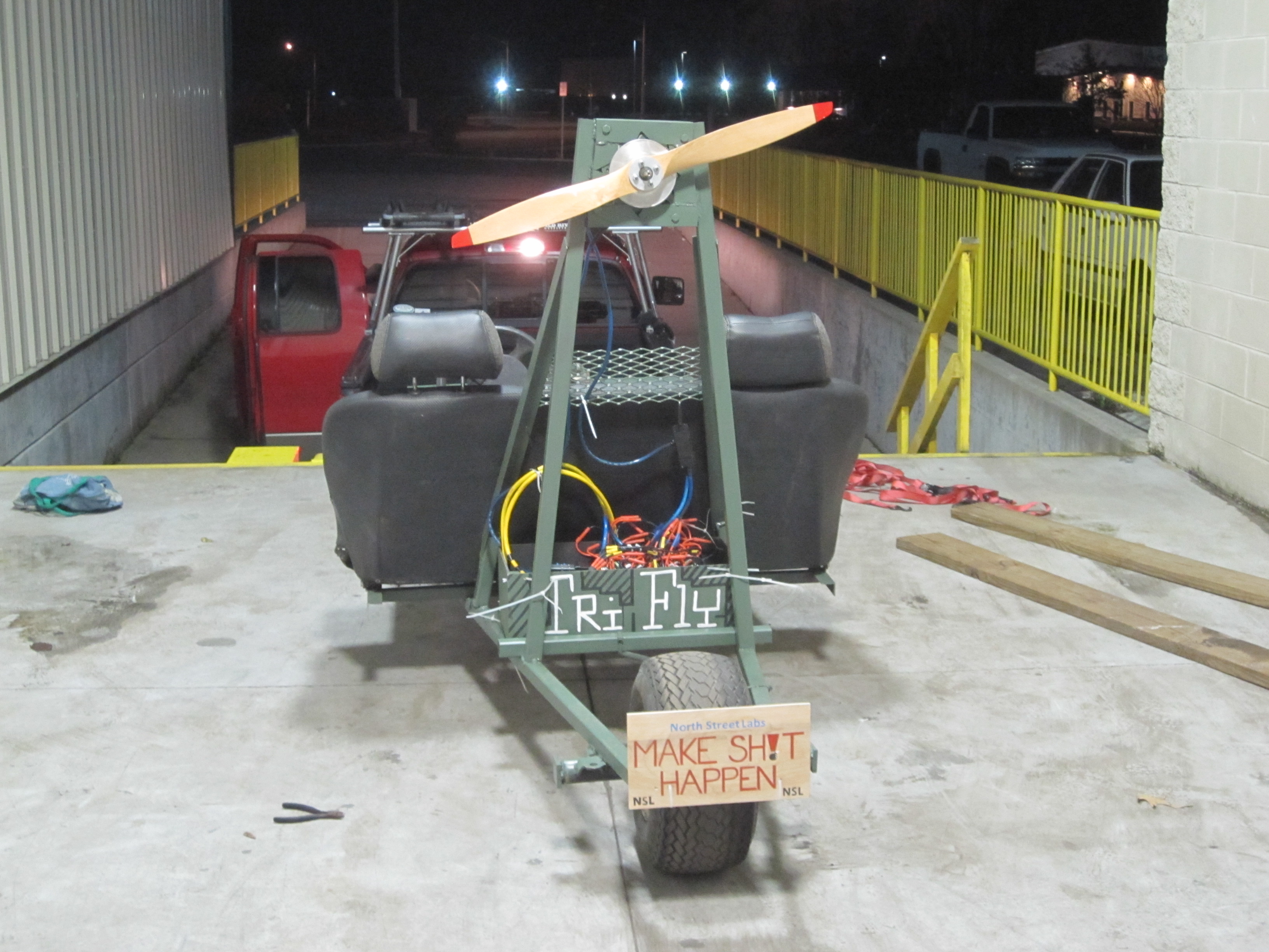
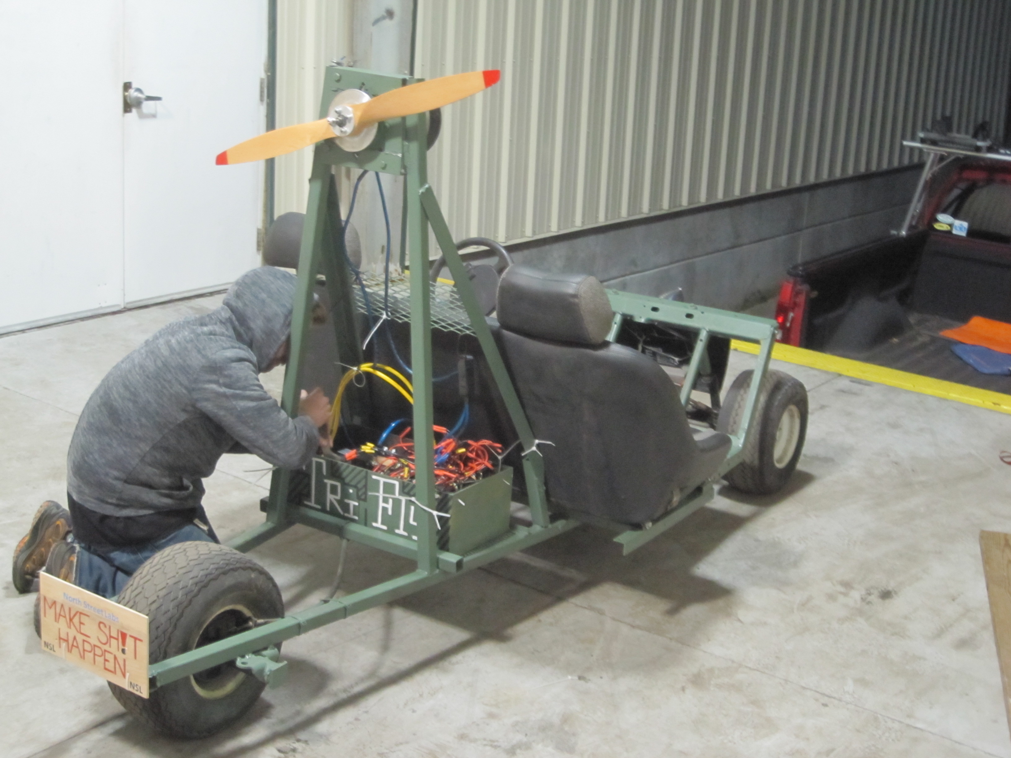
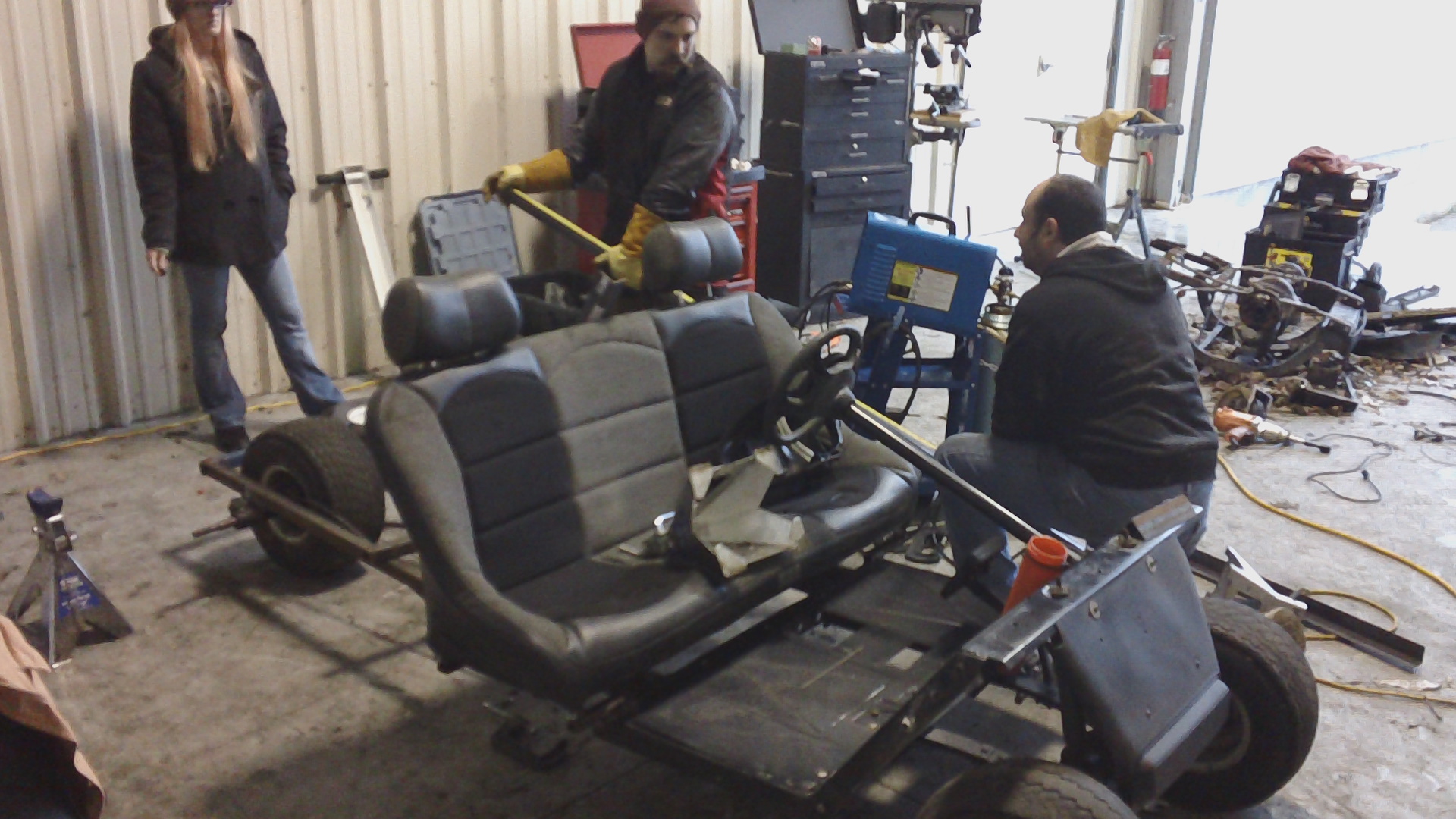
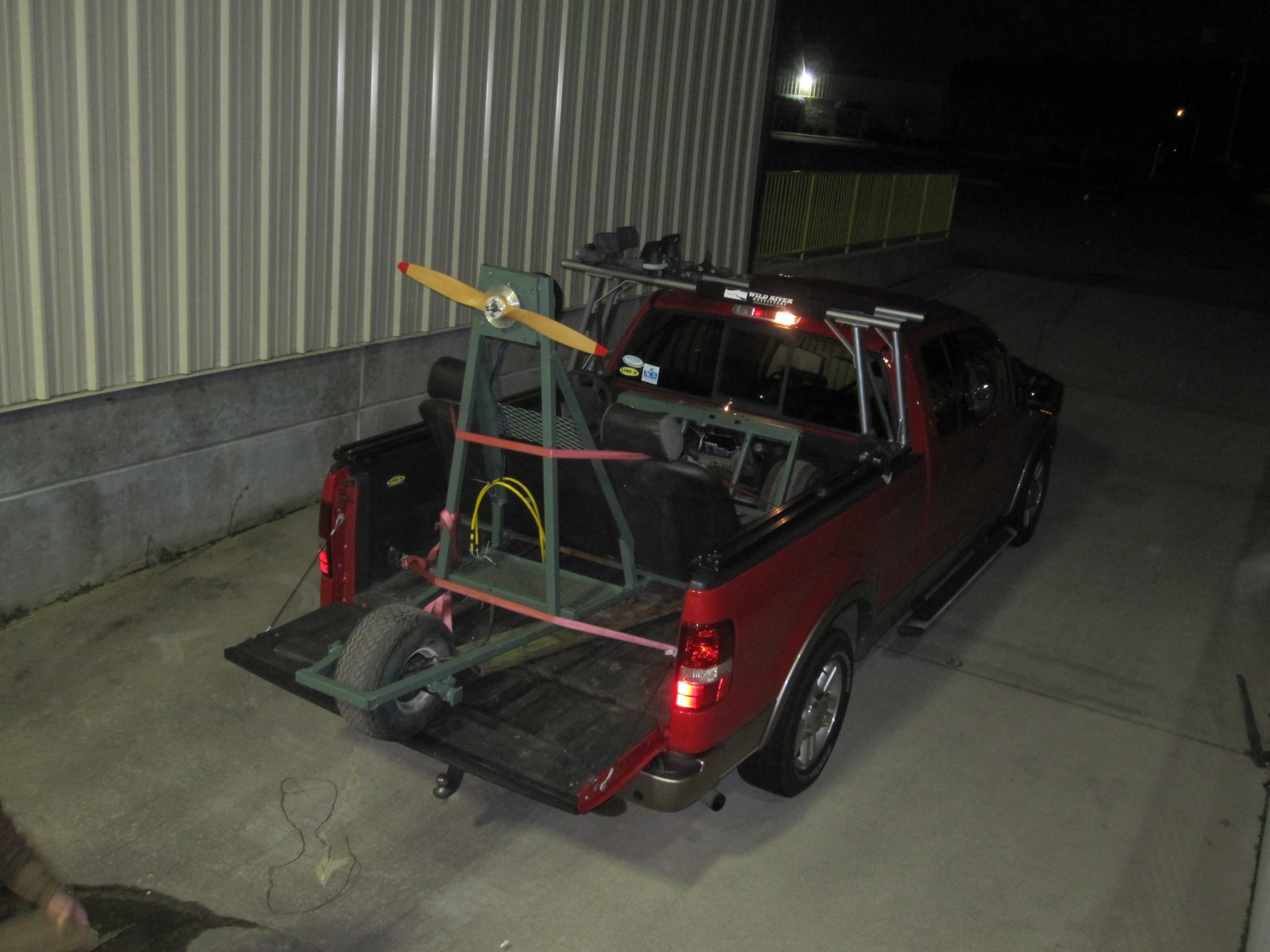
We had 48 hours to make something for “The Deconstruction 2013.” For our build, we took junked items apart and transformed them into something fun and awe inspiring! The end result is The TriFly, a 3 wheel electric propeller driven land vehicle!
Basic build details:
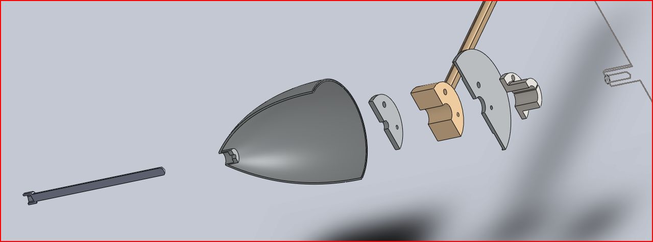
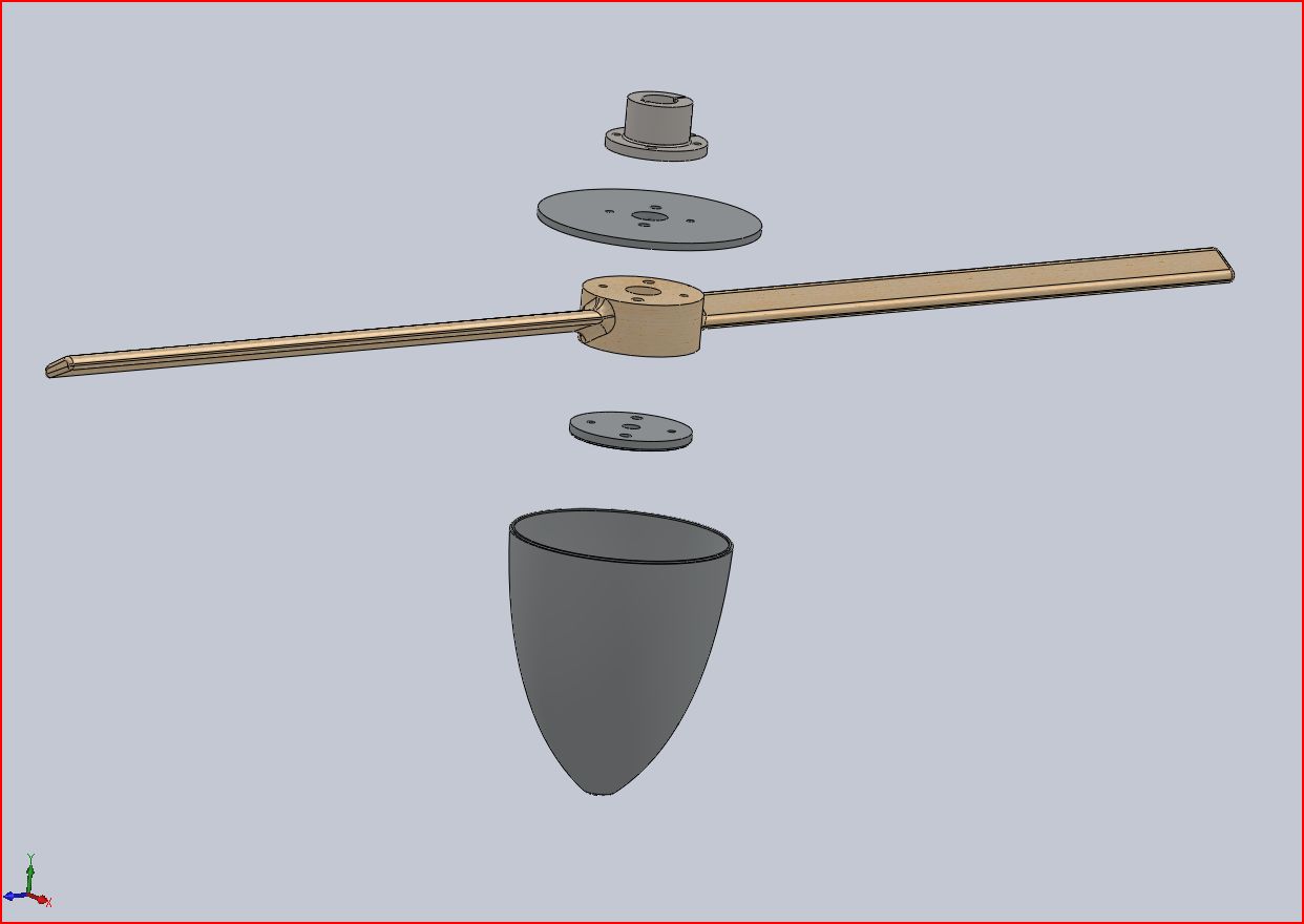
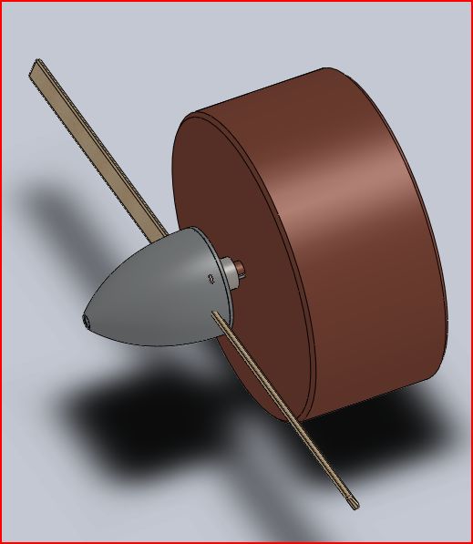
20 HP (continuous) 72v neodymium motor
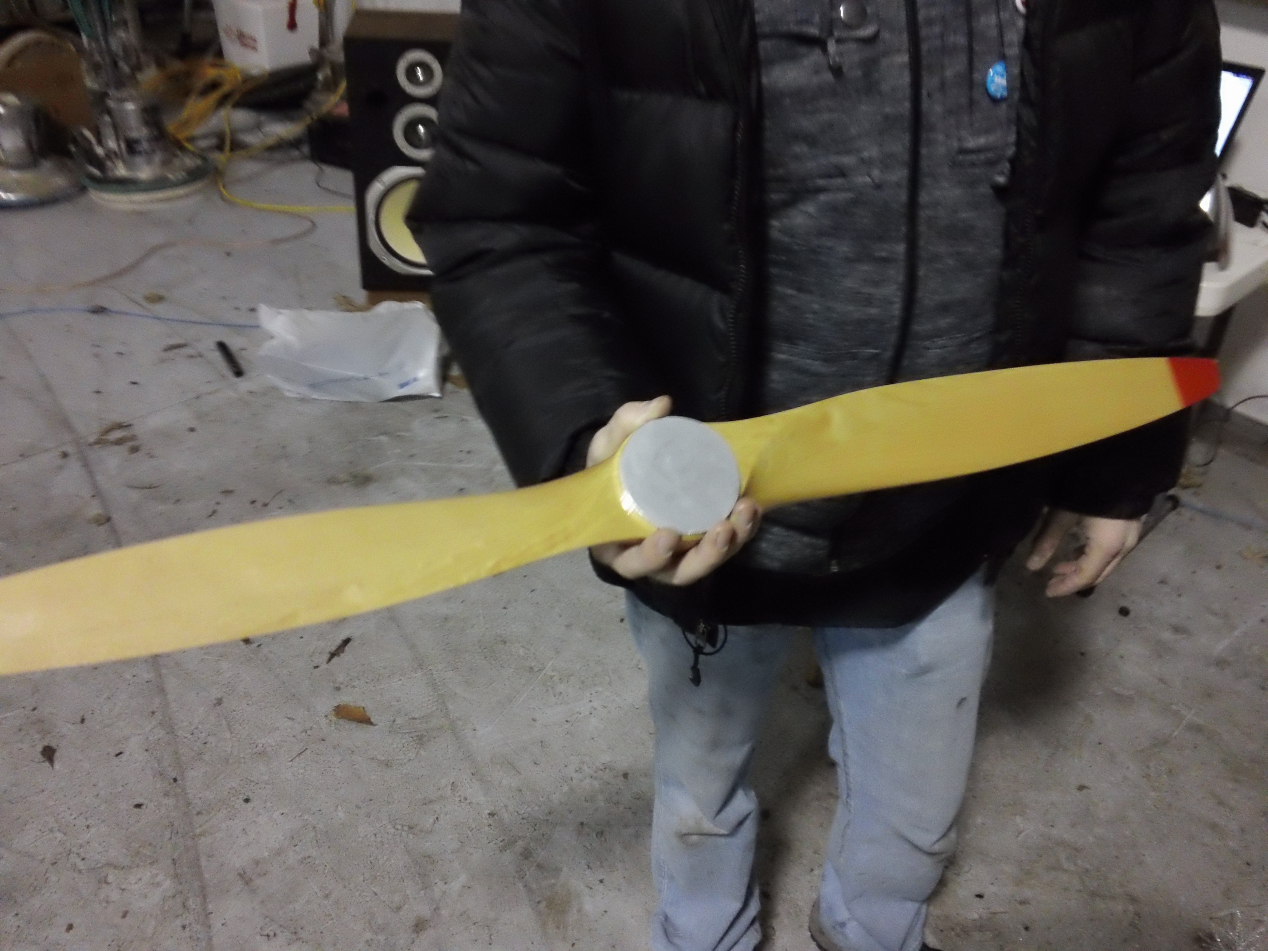
36×12 cheapo mass produced beechwood hobby propeller. Wish we could have got larger!
2 junked golf carts kindly donated from ODU.
Ultra powerful demonic red projector LED’s from a scrapped theater projectors
speaker housing for mounting lights
Glass shower knob adapted to throttle
“Racing” Ford Bronco bench seat practically given away on Craigslist
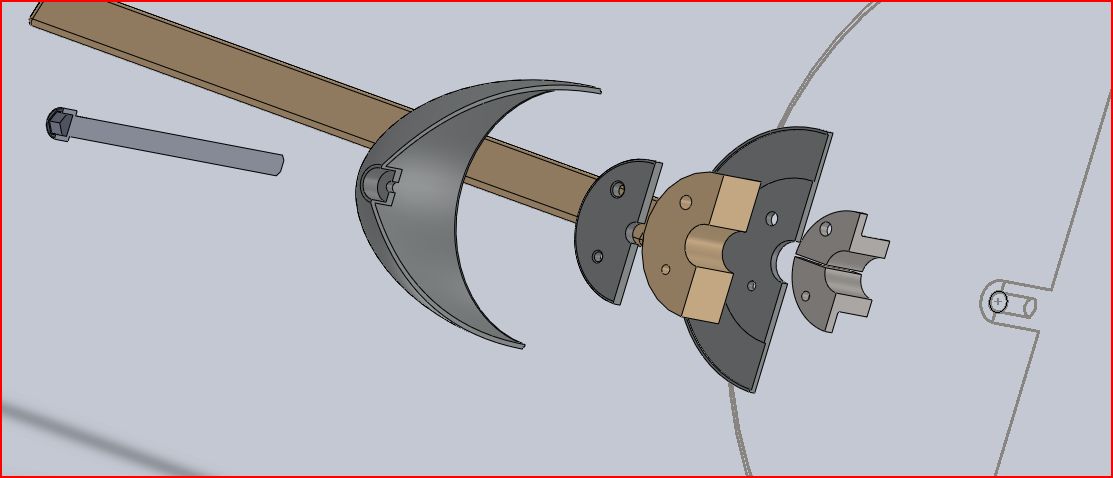
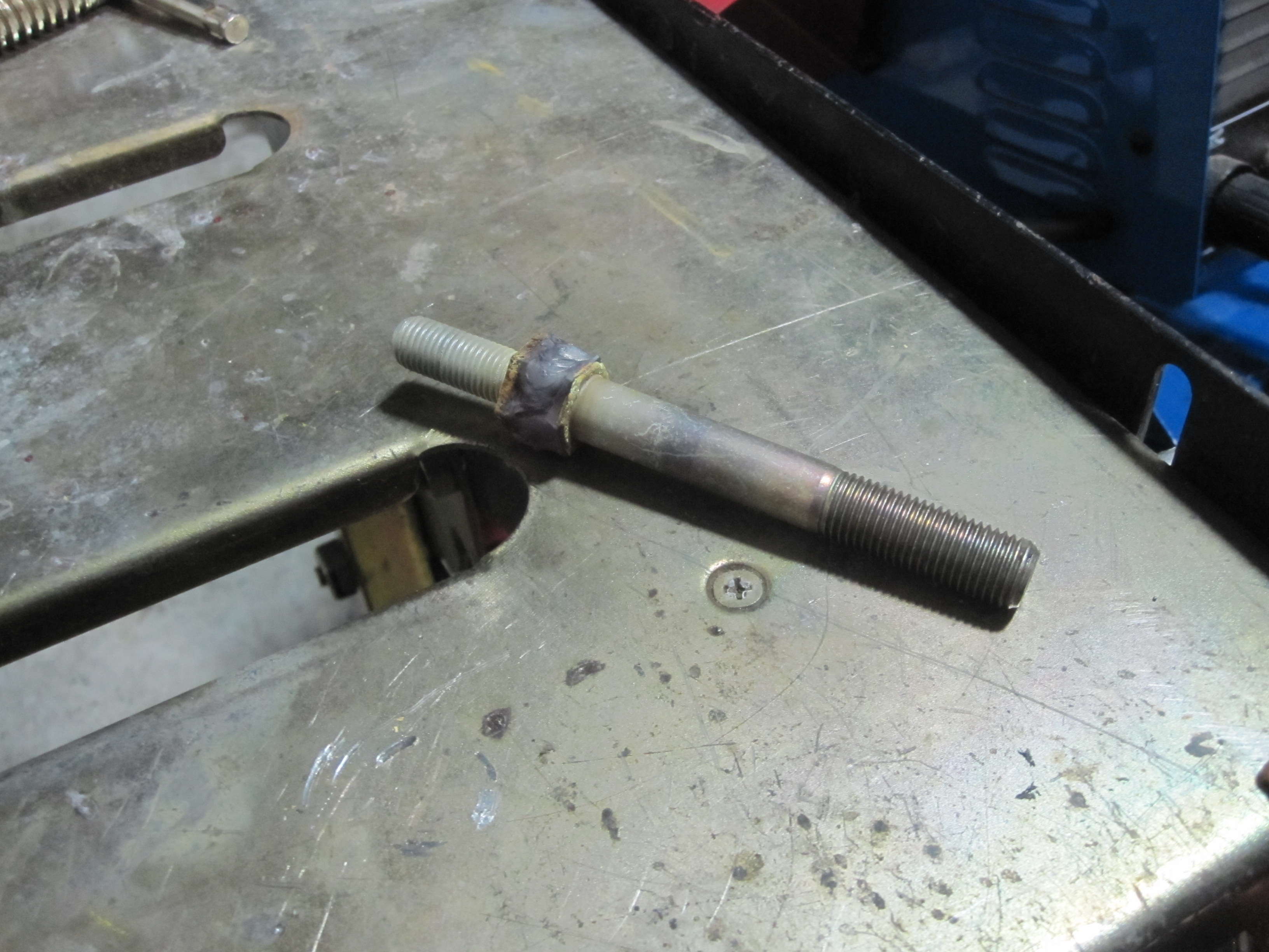
We custom machined adapters with our metal lathe to mount the atypical motor to the propeller
Old 4 AWG car stereo wiring and distribution blocks from highschool a decade ago
Probably a lot more we are forgetting, we are still recovering!
These parts were aligned by custom machining an adapter of varying diameter down the shaft to perfectly center the pieces so it could be drilled out perfectly.
Loading it on the truck after the build!
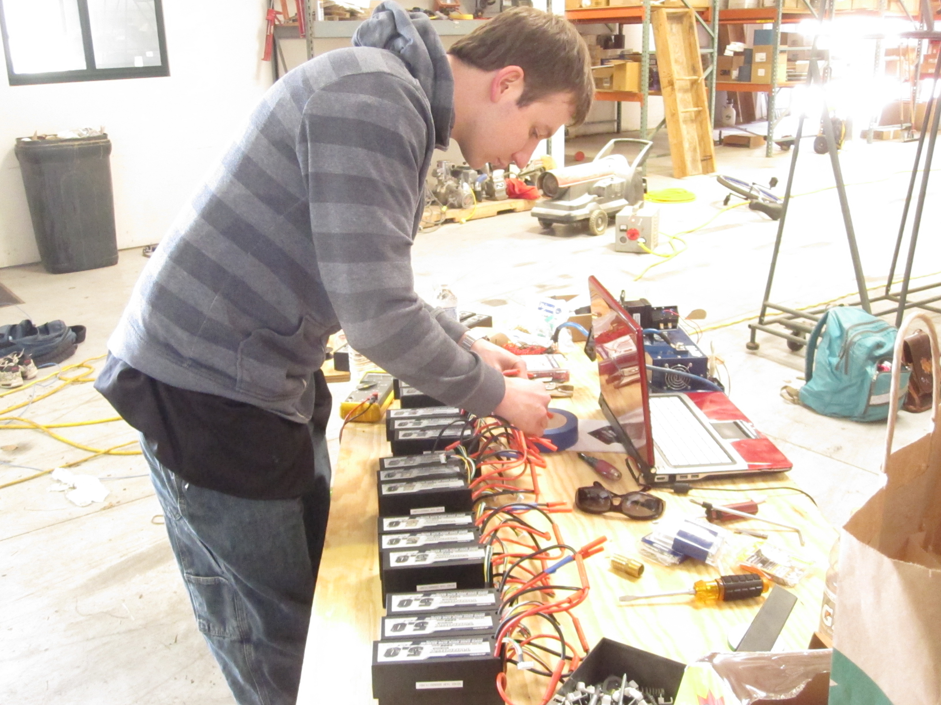
Battery Chaos. 30 5AH 14.8v nominal packs in combination series & parallel. 2.2kWh of fury.
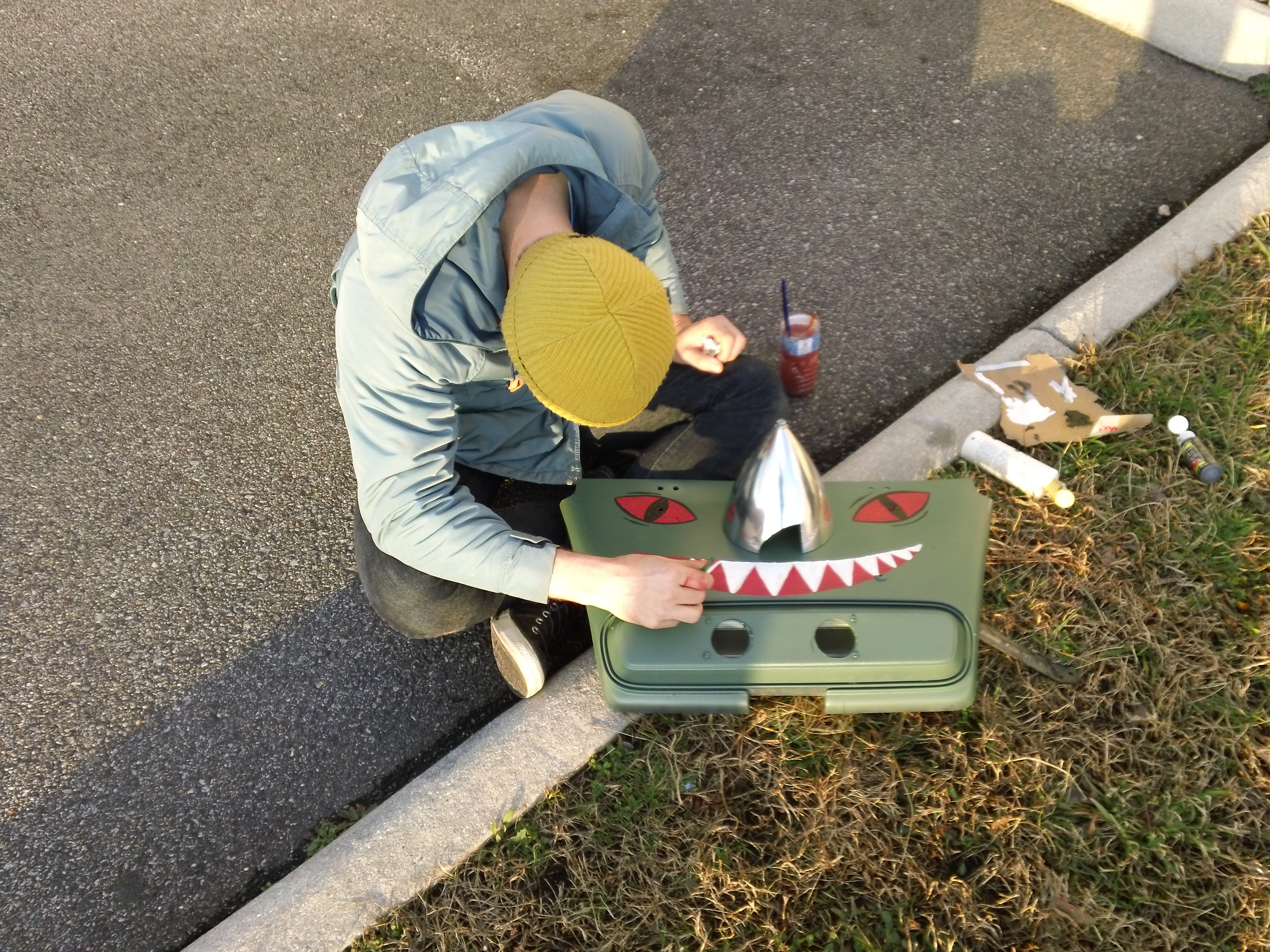
Demonic front end.
CNC machined an aluminum disk for the prop.
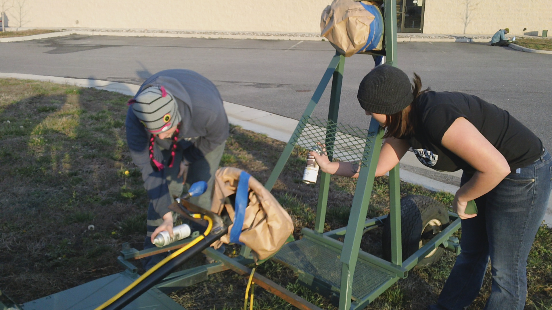
Grunt work from random helpers!
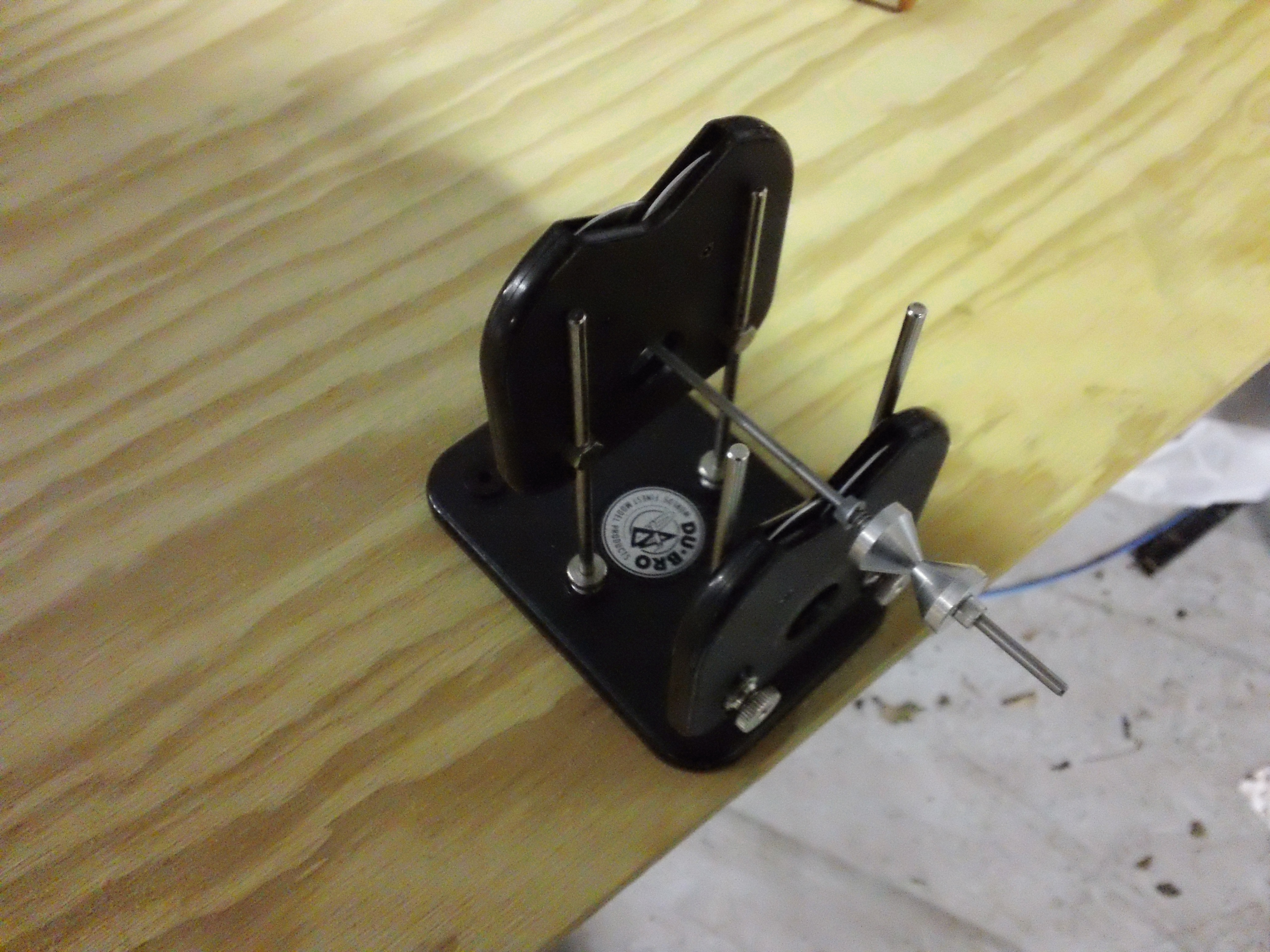
Cheap prop balancing tool.
Fabricating things up. These seats caught fire about 9 times during the process of welding around it.
George Norris adding some character
Welded together our own hardware for prop mounting because nothing was available to fit our needs locally within our time constraints!
The famous motorized hammock that started some of our fame is now for sale! On Etsy.com you can purchase the one of a kind Drivable Hammock, this beautiful machine will make all your dreams come true!
Update! 11/18/12. See bottom of page for updated video and pictures of upgrade.
History and Precautions:
Laser technology has come a long way. Back in the day, the first compact disks came out using infrared lasers. People demanded more information to be put on a CD. Eventually the DVD player came out, and this was made possible by shorter wavelength red lasers that could store more information in a smaller area. The need to copy these disks necessitated higher power lasers, and thus burner diodes were born. The hacker world very quickly dissected these to make very strong portable lasers. For reference, this is 300mW:
Some new players have emerged over the years with the quest to jam more information on those same size disks. Blu-Ray, which honestly should be called “Violet Ray,” uses a ~405nm wavelength diode. They started off weak, just as the DVD did. Now, there are burners which can pump out hundreds of milliwatts just like the DVD’s. For reference, a standard legal red laser pointer is under 5 mW. This is an adjustable low power bluray pointer we made a while back. It appears blue because my camera sucks, but looks violet in person:
Low Power 5mW Blu-ray testing
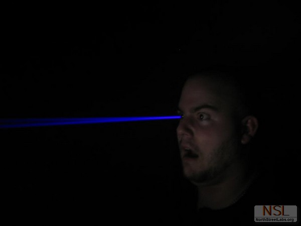
In addition, high powered lasers have also recently found another use in projector technology. Some brands now utilize extremely powerful blue lasers as the light engine for the projector image. I will spare you the details on how they convert the colors, but the punchline is blue lasers are now terrifyingly powerful. We are talking ~2 WATT capable from a single diode. This is about 400 times more powerful than a regular laser pointer. It burns skin and objects instantly, and one TINY mistake will have you blind.
These are my laser goggles. The one in the back left is for the ludicrous wavelengths. Before you make a laser, BUY THE GOGGLES FOR THE RIGHT WAVELENGTH AND POWER RATING.
Disclaimer:
The information I am posting is aimed to be educational. I do not endorse illegal use of lasers, and I encourage that all proper safety equipment is used. Follow all local laws and ordinances before engaging in building or using these devices. I am not responsible for any illegal actions used as the result of this information. The responsibility is purely on you. Don’t go blind, and don’t go to jail doing something stupid!
People asking me to build/sell lasers for them:
This is a combined response for the countless inquiries about details for making, selling, and producing parts for them. Let me start by saying we will not be able to sell completed lasers of this power level for obvious legal reasons. Building them yourself is fine, but selling them on our end is just not possible. We are primarily a maker space that simply enjoys creating things, so most of the things we do are not aimed for sale anyway.
On occasion, we do sell things locally just to recoup costs of materials so we can continue doing what we do. I would have no problem selling a custom heat sink to an intrepid tinkerer that wants to learn about lasers and LED lighting. We might make a few and put them on our website in the near future; for those who asked, I would periodically check in for updates. There are plenty of hobbyists who already sell parts online as well if time is of the essence.
I would strongly urge those who have no experience making lasers to start out with a far less powerful diode than we used. There is ZERO room for error with Class 4 lasers, and I don’t want inexperienced people to rush into something they’re not prepared for. Safety first. If new to the hobby, start readng up on some laser hobbyist forums; they’re great sources of information. Be prepared to spend at least $80-100 on proper safety gear alone. (Do things right, and please don’t be careless around others). It’s a small price to pay in comparison to permanent eye damage and thousands in medical bills. That being said, creating something amazing with your own two hands can be incredibly rewarding.
Those requesting more educational information have been heard, and we will try to update the website to address any further questions.
The Build:
The plan was simple. Take a nostalgic NES “duck hunt” Zapper, and retrofit it with a ridiculously powerful laser.
I started by unscrewing the traditional zapper and inspecting the stock components.
You can scrap the electronics in the barrel of the gun entirely. Just unclip the wiring harness, and the whole cord comes right out with the unnecessary components. The switch and trigger mechanism is kept.
I was worried that the OEM electric momentary switch wouldn’t handle my power needs, so I checked it out. It turns out Nintendo completely over engineered it, and the switch was more than capable handling ridiculous levels of current.
The factory trigger also turned out to be perfect; a full trigger pull does a momentary pulse exactly how I wanted. The stock design also allowed for a partial trigger pull for rare occasions I wanted a slightly longer burn time.
Desolder the electronics from the switch and throw it away (or reverse engineer it for some other project).
I reassembled the switch to the trigger housing, and I did a quick “proof of concept” test with a crappy 5mW red laser module. It works perfectly.
Video of trigger action:
Now it’s time to make your power wire. Cut extra long length so you don’t come up short when connecting things later. Pre-tin youre wires.
I had to heat-shrink both sides for this terminal.
Coming together. Yes, the wire size is excessive, but doesn’t hurt!
For those worried about wires being too small during your build, some number crunching:
When I started this project, I honestly had no idea what kind of batteries I would be using. I liked the simplicity of a single cell, but the common cylindrical designs were just too shitty or too large for the handle location I chose. In addition, I would be forced to use a boost driver to get the voltage up up to lasing level. I aso wanted to keep the weight in the handle for balance & feel.
I diced up the interior plastic retaining box for the metal weight. It was slow and tedious, but easy with the right tools.
The space was mostly clear, but it looked messy and had some rough spots still protruding in the way.
I used a “beater” soldering iron to easily melt down sections of plastic that were stubborn to cutting.
For reference, I am including pictures of different types of batteries so you can decide what you want to do with yours. After clipping and melting away non-essential plastic, you should easily be able to fit two 16340//RCR123A even while resting in a battery case.
You will have to clip away select plastic supports to make room. I cleaned up cuts and made things flush by doing more melting with my “beater” soldering iron. You would probably have good luck with a hot knife, but I don’t own one and work with what I have. Just have a rag handy to wipe away plastic so it’s not burning away on your tool.
Keep your laser leads together until you’re ready to mount to your driver to reduce static charge. In this build, I am using a 445nm M140 diode.
It was time to mount my diode to an AixiZ host to get enough heatsinking for soldering. Let me start by saying that there are actual tools you can buy to do this quickly and flawlessly every single time. I don’t own one of these tools, and I am impatient.
I included this section to show how to do the full process, in case you don’t purchase a completed module and want to do this yourself with common tools:
You basically just need a flat open cylinder small enough to push it into the housing and not crush the leads. I found a socket set and started pressing the diode in that way.
I put it in a vice to partially seat the diode.
Now, the proper position for the diode is NOT FLUSH as seen in picture below, but pushed in a bit further. You can clearly see how far to push it in when you really inspect the AixiZ housing (a few pics up); there is a lip inside the housing where the diode stops; this makes better contact for heat transfer. If you are uncomfortable simply pressing it with guesswork, either buy the mounting tool or measure the exact distance with calipers so you know how far to go. Just don’t crush it!
Naturally, I was late to find out about the proper positioning, so I had to go back half way through this build and push it in further. That’s why I don’t have pictures to show proper seating. It’s basically just pushed in a bit further. Oh well…
On a slightly unrelated note, take a moment to look at the diode’s leads below. The diode was properly shipped with them connected by a little ball of solder; shorting the leads like this reduces the chance of static discharge before you’re ready to solder connections.
Since I was desoldering the connection, I maintained it with this nifty clip. It also doubles as a method to pull heat away from the precious diode!
Solder your laser leads quickly to minimize heat to the diode. I was extra paranoid about heat transfer, so I placed aluminum plates around it to help.
Heat-shrink the leads for protection.
I did a quick test on a small driver to make sure it was still working, and everything was fine! When finished testing, short your leads again.
You can buy premade heatsinks for your laser housing, but we wanted to make our own. We designed the heat-sink to serve 2 functions. Obviously, we wanted a little better heat transfer.
We also wanted our design to effortlessly hold the laser dead center for accurate aim with the gun’s iron sites.
It automatically centers between the internal plastic supports with minimal adjustment! We started taking measurements of housing diameter (AixiZ) and stock plastic locations we wanted to take advantage of.
Sexy.
Depending on factory variations and drill bit sizes you have, you might need a set screw to keep your AixiZ housing in place.
Preferably, your AixiZ housing is tight enough to press fit. I initially used a set screw, but then I found another AixiZ housing that was tight! Factory variations are annoying. I’m leaving the whole process here for whichever method you do:
Apply thermal compound lightly around the housing. Use just enough to very lightly surround it. I dabbed and smeared with a paper towel.
We drilled a hole for the set screw. I don’t have a collection of set screws, so we literally just went digging through our junk part bin for something that would work and found a matching drill bit:
Aluminum is soft. Our random set screw was strong enough to thread the aluminum by itself. We just dremeled off what wasn’t needed.
If you plan to remove your set screw, dremel in an indentation for a flathead screwdriver. I ended up having to take it out this way after threadlocking, all to go back and properly seat the diode. Frowny face.
I decided to give small Lithium Polymer (LIPO) packs a try.
They have a nominal voltage of 3.7v with a peak of 4.2v at full charge. I wired the packs in series for a 7.4v nominal (8.4 full charge) supply voltage. Each pack is 750mAh rated, a relatively small capacity. The discharge rate, however, is very impressive. It’s designed for RC vehicles boasting a “35C-70C” rating, meaning it can safely drain at a rate of 35x its capacity: way higher than the total drain of my laser driver. The charging circuit goes out the Zapper handle’s stock hole, and will automatically balance the cells with my charger. At the time of this build, I’m just waiting for the RC “2S” balancing plug to come in the mail to finish it! I also have a tiny circuit to connect to this RC plug with voltage read-out and alarm, so I never over discharge! As is, a full charge should be good enough for approximately 30 minutes of run time.
Here’s the plug i am waiting on to easily integrate charge/balance of my cells:
I used a 2.1A buck driver, “X-drive” from CajunLasers. This is a lot for this diode, but should be fine for my momentary duty cycle. Buck drivers require the supply voltage to be above the Vf (forward voltage) of the laser diode… which is in the mid 4v range. One Lipo cell alone wouldn’t have been enough voltage for the job.
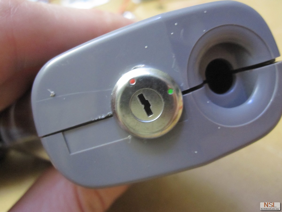
I started thinking this is going to be a really serious laser, so I should install some safety on it. I had a turn key switch, and I decided to toss it in the base. I just took my trusty “beater” soldering iron again and poked a hole where I wanted it mounted.
Snip way melted plastic with wire cutters to make it flush.
These key switches wire in series with the whole circuit; they handle the power fine. I believe I ordered them from Sparkfun a long time ago.
Hot glue works awesome for holding stuff like this in the position you want.
Pre tin your connections to make things easy.
If you are using a 2 cell configuration, wire them in series to add voltage. Google series wiring of batteries if you can’t figure it out by the picture; it doubles your voltage but capacity remains the same as 1 cell. (Parallel wiring doubles capacity, but voltage stays the same).
Now just wire the whole gun in series. The key switch breaks the connection with your driver, as well as the trigger.
Before wiring to the driver, DRAIN ANY CAPACITORS ON YOUR DRIVER BOARD. Just short them out with wire or any metal contact. If possible, wear an anti-static ground wrist-band while soldering as well. Do everything possible to keep your diode safe!
This driver does not require heat sinking for the short duty cycles I am working with, so it’s fine as is!
Now just complete the circuit and put things back together in the reverse order of how you took it apart! I threw on a couple last second rubber O-rings around the heat-sink to improve the centering.
Once again, WEAR YOUR GOGGLES. DON’T GO BLIND.
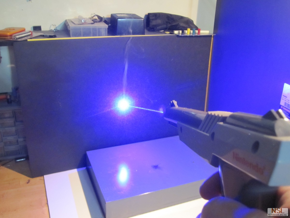
After initial testing, this thing is absolutely terrifying. I discovered that my laser meter tops out at 2W… which this Zapper rapidly passes. The meter quickly shoots to 1800+ , then just says “1″ when topped out. This means the Zapper is AT LEAST 2W OUTPUT. I wear my laser goggles at all times when handling this thing and only turn the key right before use. That being said, it’s been a fun build!
Update! 11/18/12
So my “2S” JST-HX balancing plugs came in the mail, and I finally had a reason to reopen the Zapper for the upgrade.
I got it to charge and balance fine on my “Turnigy” charger, but something happened with the custom female charge plug I made… probably couldn’t handle any form of current and melted the wires. I ended up simply removing it, and I do slow charge through the male balance plug.
While I was in there, I figured I would use some thermal epoxy to heat sink a bit of aluminum to the driver for a little better burn time. If curious, I used “Arctic Silver” epoxy… expensive but superior to the Alumina type.
The male 2S port also serves as a sweet voltage read out. This nifty “Lipo” voltage reader/alarm reads each cell volt, total voltage, and has adjustable low voltage alarm for over discharge protection! On ebay, they were in the neighborhood of $3-4:
A few years ago we were approached by Noah Larmz for a light show for one of our favorite shows Fantastic Planet. This spawned Noah Larmz Research & Development, eventually we renamed ourselves North Street Labs a more fitting name. We worked hard designing, prototyping and building our first large scale light show sign in just under 2 months – the Fantastic Planet Sign, a wonder of soldering, programming, in-house etched circuits, and amazing team work from all our friends! After a few years having fun and creating things here at NSL, we were approached by a newly formed and renovated venue the RVA Hippodrome to commission another light show – in short time and to be totally designed by us! We were jumping with joy to be involved in yet the creation of another party of epic proportions.
We planned an idea and sketched it with Google Sketchup, they liked the idea and we ran with it! We started buying materials, proving concepts, talking to Chinese and US suppliers. It shouldn’t be surprising that the USA is often cheaper for unfinished goods unless you are buying in bulk. Always talk to the local companies, they will often cut you a break if you are a bunch of locals working on a public project with little to no money to be made.
After countless hours of work, lacking sleep because of the Red Bull Creation 2012 competition, and general craziness – we finished the build in time before the bands did their sound testing last week on Sunday August 5th. And the show was a success! Everyone had a great time, Richmond discovered a brand new venue of beautiful design and new technology up there with some of the best we’ve ever seen. here is a clip we made of the show:
Lots of pics of the show:
Expect us back in October for another crazier Halloween party!
About the build:
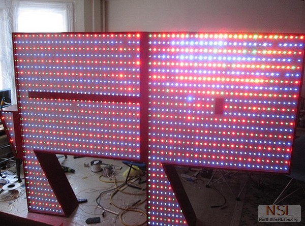
With our previous experience with subwoofer boxes, CNC machining and furniture creation, we designed simple yet elegant light boxes to help distribute the over 750 RGB LEDs that make up this display. Nine full sheets of 1/2″ birch plywood and 3 sheets of 1/4″ hardboard make up the wooden boxes, the front panels are the only things CNC’d on these boxes.
We ordered 44 LED/M 24IC/M LPD8806 strips from CLEN LED through Alibaba, 16 meters of them! With our budget we couldn’t afford to make the show awesome enough at Adafruit’s prices. Using Alibaba is extremely risky and we were hesitant, but Jack Huang an English Tourism Major working for CLEN LED was a great translator and even knew his LEDs well! You can contact Jack Huang for help here: Mr. Huang. It was a nervous order with only money order or direct bank transfer as the payment options. He assured me everything was well, and he even had them shipped to us in less than a week! They are a good company, the good guys from China, I trust them. They even included a string of 4LED/pixel squares we used in our SIMON game because I accidentally overpaid them ~$20. When you contact them, be frank, courteous and let them know what you are doing, they might actually be interested in your hackerspace project!
Each box consists of an 5v 5amp power supply from ebay, 3 have since failed. Do not buy the cheaper ones from china, or even the USA reseller as we did (Also they said 5v 4a on the inside! What a rip-off.) From now on we only buy nice power supplies. There is an Arduino UNO Rev 1 in every box, connected to an RS485 MAX485 breakout board. They receive data from the MASTER by a serially connected RS485 bus. And finally 86 RGB LEDs and 43 LPD8806 ICs in each box, a total of 688 RGB LEDs!
An Arduino MEGA 2560 serves as the brain of the system controlling what each light box does, it is connected to several SparkFun EL Escundo Dos boards, an MSGEQ7 7-band equalizer, an adjustable electret microphone, an RS485 differential transceiver, and a 240w 12v power supply that wasn’t nearly as bad as those pesky 5v 5a ones.
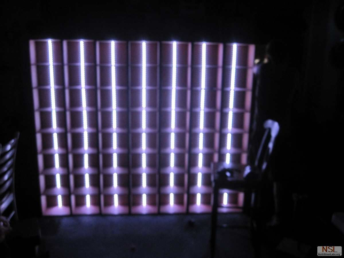
There is an impressive amount of EL wire too, White, Blue and Red EL Wire total over 300 feet! Between several 12v high output inverters and the EL Escundo Dos boards there is stimulated lightning and strobing lighting towers! The EL wire is attached to “lightning towers” which are actually three Lightning Arrestors welded together to a 1″ square tube of steel, which bolt directly to the stage. All the lightning EL Wire is strung from the main controller, up the back of the lightning towers and towards the ceiling/wall/speakers with the help of staples/Gaff tape. The effect is hard to capture but beautiful in person.
We had problems finding a good diffusion that wouldn’t lose too much light. Baking sheet looked the most promising (especially for the cost – $5 would provide us all we needed) But it wasn’t as blindingly bright, looked more like a nice multicolored lamp. We wanted to use a particular ROSCO Gel used in theatrical lighting, but that would cost well over $200, we settled on Privacy Window film two layers thick to achieve the best diffusion. The light is bright, and diffused, but it is NOT dimmed by any means, like any tracing paper/baking sheet caused. We wanted to paint/aluminum foil the interior, but time was against us. For those paying too much attention, one box was not used because of technical issues from a power supply explosion. Again, a nice power supply is EXTREMELY IMPORTANT!
The wood was glued, clamped, and pin-nailed over a couple of days. Then slowly the circuits were assembled, wired up, tested. A few problems were found and painfully fixed, pro tip: Make sure soldering on the strips work before removing the adhesive backing protection. Cold soldering joints are easy to do when you are trying not to overheat these strips, we had a few of these. Don’t do this, it’s irritating to fix if you’ve already installed them.
Here’s a small video we made when we realized it actually worked!
Several sub programs were written, combined and reprogrammed to work again. We used the PS2X and EasyTransfer library from Bill Porter, and the LPD8806 library from Adafruit. The PSX controller is one of our favorites to use, there are many buttons to choose from, joysticks to manipulate and more if you dive deep enough. You can get our current working code here. This code relies on a PS2 controller connected to an Arduino and uses TX to communicate to an Arduino on the RX line, as well as using the hardware SPI on the Arduino UNO for controlling the LPD8806 strips. We needed that extra distance, so we used MAX485 transceivers to allow hundreds of feet between connections. If you have any questions, shoot us an email below.
Right now the code above consists of Smart Boxes, but a dumb command center. Below is the code we originally developed for data sending upon the RS485 network, it assumes a smart controller and dumb light towers, all the light towers should know how to do is turn 8 pixels of 24 bit RGB data into 24 bits of data for the 86 RGB LEDs. This is a simple way to control the 16,512 bits of 0s and 1s that make up a single “frame” of the entire light show. However my code below refuses to work, and I settled on the crappy code linked above.
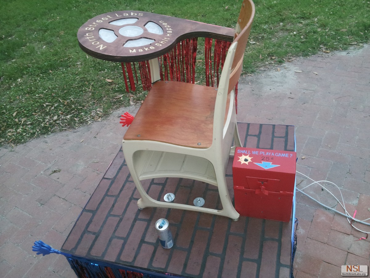
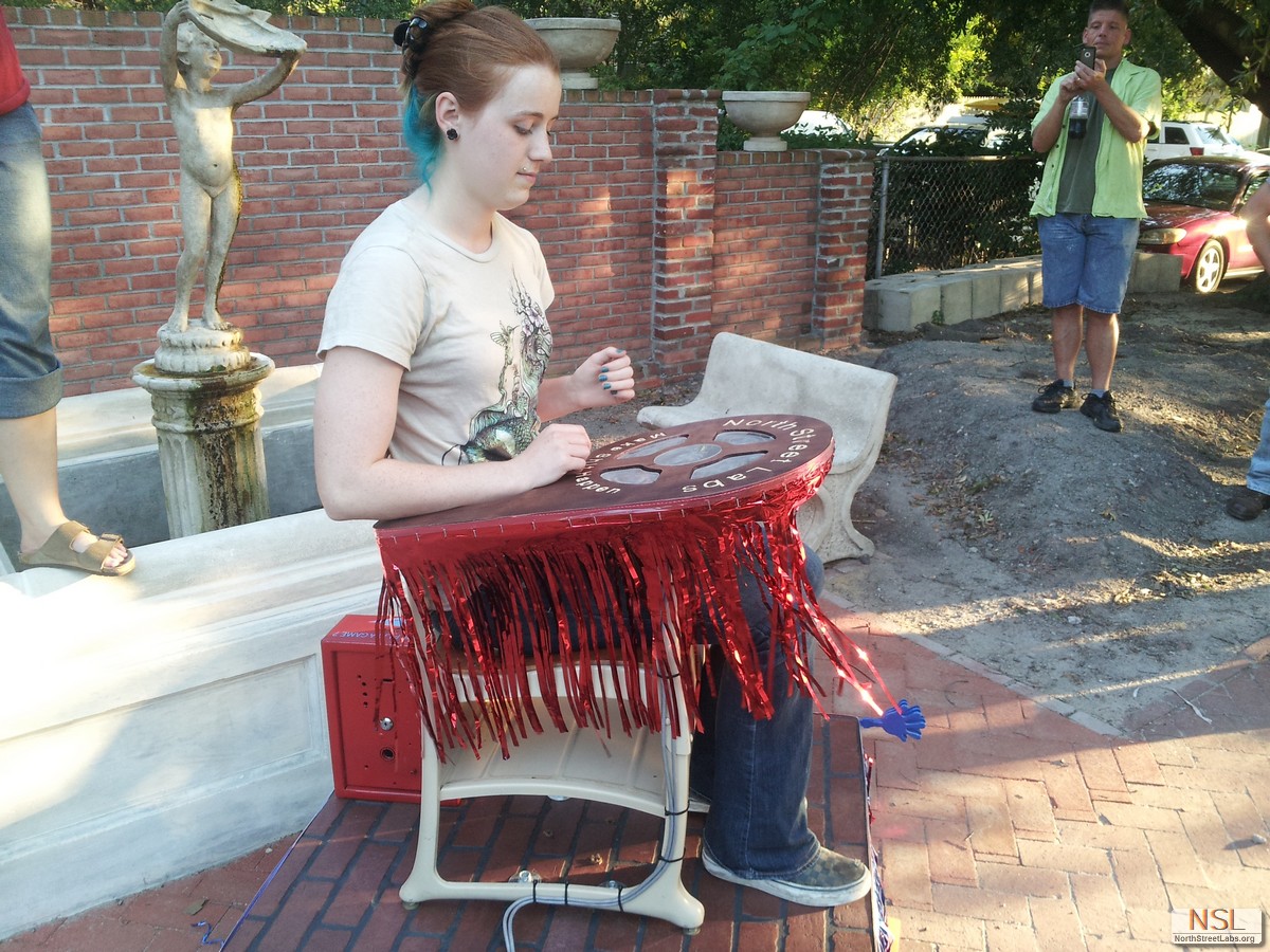
A little while ago we received a Bullduino from Redbull, and then we made something with it. This year in the second annual RBC, we’re trying our best to qualify for the finals. We made an insanely powerful game, Simon: SHAKE!
The unsuspecting game player walks by, but we trigger buttons on our wireless controller to make computer beeps to get attention. The suspect inserts a coin. When a coin is inserted the game begins, as a typical Simon game. Once the player gets farther than 4 correct answers, a failure then triggers the 2000 watt floor buffer to vibrate the platform and player while flashing bright red LEDs and making loud noises!
To do this project we interfaced the Bullduino to many devices::
PSX wireless controller
25Amp 600V Triacs
2000 watt industrial floor sander
2 speakers via 30 watt amplifier at line level voltages.
20 RGB LEDs
4 push buttons
Coin slot detector
Most people were more than adept at playing Simon, which led them to get deeper and deeper into thought as they memorized more. Eventually they are all caught off guard when the machine gives them a shake! This machine is so violent, it is hard to capture on film! Luckily we did! The machine managed to break apart our first set of buttons, wiggle free all the wood screws, and even a few bolts! After hot glue, thread locking, and some hammer time dancing it was solid as a rock.
The desktop was made by measuring our LEDs, buttons, and the desk. We then modeled it all in CamBam to generate Gcode for a new desktop composed of three layers to help hide wiring and electronics. We engraved our name and our slogan “Make Sh!t Happen” out of necessity to keep everyone happy.


